It is hard to find a milling machine worth anything these days, that does not have a brushless motor in its spindle. Brushless motor technology has also revolutionized other industries, from electric cars and trains to hand power tools.
We are the only builder of vibratory stress relief equipment in North America that uses brushless motors, which we use exclusively. Why use anything else ?
Learn more on our Equipment Comparison page.


FEATURED VSR APPLICATION :
18 m Ingersoll Gantry

Ingersoll Machine Tools has been a user of our VSR Process since the 1990's. In the early 2000's we stress relieved a series of 18 m long gantries for them. Later Ingersoll bought their own VSR System, which they still use today. Above is a dimensional accuracy and stability profile of one of the final-machined gantry's ways, over the full length roughly 700". The two hill-shaped curves are profiles taken two weeks apart, both curves cal'd on the left, (labeled DEVIATION INCHES) showing this gantry being straight within + / - 0.0025 inches or ~ + / - 0.064 mm.
VSR Setup shown on the right, and also during assembly.
The length-wise line seen on top of the gantry, along with the lite-yellow material on the floor, is Oil Dry. This was placed on the gantry to define the nodes (low amplitude locations that appear during resonance). Two peaks were treated during the stress relief, one being a bend mode, the other torsional (twist), based by the nodal pattern. See VSR Physics. Placing the vibrator near a node is often a good location.
The valley shaped curve is the difference between the two, cal'd on the right, indicating that the gantry remained dimensionally stable within 0.0008 inches or ~ 0.02 mm.
The VSR Report showing the workpiece, VSR Setups and Charts, together with this and more dimensional data can be seen here.


WHY AN INVESTMENT IN AN ADVANCED VSR SYSTEM IS YOUR BEST CHOICE
System :
- Software plots not only workpiece amplitude vs. honest vibrator speed data, but also vibrator input power. This provides the operator the info needed to achieve the best practice VSR setup
- Super-low-noise, clean vibration data makes clear to the operator the steps needed to perform the VSR Process
- Only the newest technology components, from motor drives to PC's to motor technology
- System-wide plan to prevent excessive heat or vibration assures years of high-reliability performance, designed by PM (Preventative Maintenance) heavy-industry professionals
- Resonance-based vibratory stress relief is both most effective and fastest, as shown by independent research
Want to see more ? Go to VSR SYSTEMS
Console :
- Double-gasket sealed enclosure prevents dust, dirt, oil or sprayed water from entering the enclosure, whether in storage or operating mode (NEMA 4 / IP65), preserving long-term electronic integrity.
- Full powder coated with galvanized
rear panel (motor drive mount)
- Allen-Bradley motor drive with xternal heat sink
exhausts 80 % + of heat outside the enclosure
- Full-ground plane design using the Faraday Box
concept prevents EMI noise from entering or
leaving enclosure together with process signal
isolation between motor drive and PC keeps
vibration data clean and clear
- CNC machine tool grade 15” / 380 mm
touchscreen display has no mechanical
elements, such as fans or rotary hard drives.
- Main-Frame construction with removable back
panel, so that advances in motor and motor drive
technology can be installed easily.
- Embedded OS
Vibrators :
- Speeds up to 12000 RPM (yes, 200 Hz ! ! ), which greatly expands the range of workpieces into both the very rigid and heavy and those of modest size
- Tight speed regulation, as low as 0.03%, with no warm-up drift, a problem that plagues motors with brushes
- Thermal sensors protect the motor from heat, with full display of motor temperature
- Dual flanged vibrator (Model 8a and 8b) can be operated in any orientation, which is mandatory when treating certain workpiece shapes, such as large rings.
- Rugged connectors with spring strain reliefs keep cabling functional, even in tough industrial environments
Combining these elements, together with our robust technical support has allowed dozens of shops to produce a steady stream of dimensionally stable, accurate, predictable precision parts.
Site Title

VSR Treatment Chart made using a Model 7.5 VSR System. Upper plots are acceleration, before (green / baseline) and after (red / documentation) stress relief treatment. Note that all resonance peaks grew, while the broad peak at ~ 3600 RPM also shifted slightly to the left. Upper plot is calibrated in acceleration / g's. Lower plots are vibrator input power, again green = before / red = after. Poor vibrator location would result in much higher power peaks, thus the importance of plotting power. Horizontal axis is RPM. To see the VSR Report containing this chart, click here.


Aerospace tooling for the SpaceX Program is setup for VSR Processing, using a T-slotted fixture. U-shaped workpiece was clamped in three spots (minimum number to determine a plane) and raised / separated from the fixture by 3/16" shims (one visible in left foreground). Stress relieved in 1 hour.
Advanced VSR is a company that offers vibratory stress relief equipment and services, and has been a pioneer in the field since the 1980's. The fact that resonant vibration is most effective in relieving stress (several independent research papers state this point) and that vibratory stress relief causes a workpiece's resonance peaks to grow, shift or a combination of both, are just a few of our many discoveries.
Our research has been published by both the ASME and ASM, copies of which can be seen in our VSR Technical Library.
V16 diesel engine blocks are one of many VSR applications. According to Frank Janiszewski of Superior Die Set, Oak Creek, WI :
" We have been using VSR Technology for more than twenty years. One particular application is noteworthy : V16 engine blocks diesel or natural gas generators.
Prior to using the VSR Process, the success rate for achieving final machining tolerances on these engine blocks was less than 50 %. After these blocks were regularly VSR Treated between rough and final machining, that success rate went above 95 %.”
Line bore tolerance was 0.04 mm, full length.
After VSR Processing was started, more than 95% met this critical tolerance.
Superior Die Set has been using VSR Technology for 20+ years and is currently using our Model 8b VSR System, and discusses their use of VSR and its benefits on their website : https://www.supdie.com/vibratory-stress-relief/
VDW / Vibration During Welding :
Controlling Welding Distortion Safely


VDW / Vibration During Welding
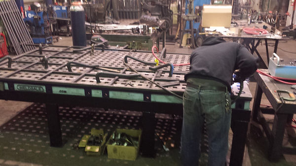
Drill rig masts which telescope together are being welded on left, with distortion kept to 3 mm over 5 m (1/8" over ~ 200") using our pneumatically powered 3D VDW System. After welding, which required NO STRAIGHTENING after fabrication, these components were VSR Processed, which allowed them to maintain excellent dimensional accuracy during machining. On right both frames are nested.
Previously, distortion / straightness of these frames was in the range of 6 to 12 mm (~ 1/4 - 1/2 inch).
VDW reduced distortion between 2 - 4 times.

VDW / Vibration During Welding, has been a method used for decades, in efforts chiefly to reduce welding distortion. Recent research has indicated that both more effective and consistent results can be obtained by using two vibrators, oriented in different directions, and running at slightly different speeds.
On left about 1/3rd is visible of a 35' leveling beam for a steel plant is being welded. Before using our VDW System, these would warp during welding by 3/4 to 1 inch or more, which required 2 or 3 straightening operations.
With VDW these remain straight within 1/8 to 3/16 of an inch.
The vibrators are pneumatic, which avoids a safety issue that occurs when using electric vibrators. In addition, these can be used at elevated temperatures, such as when preheating is required.
The VDW Video shows this work in more detail.
Welding distortion is a common problem: A survey of fabrication shops we conducted in 2015 found that many shops spend between 5 – 10 % of their shop labor time correcting welding distortion. For many years, fabricators have vibrated fabrications during welding, in hopes of reducing distortion, with a mixed range of success.
Some manufacturers of vibratory stress relief systems, other than Advanced VSR, have claimed that their standard equipment is suitable for this task. There are a few problems with this recommendation, however, the most important being a safety issue:
Using an electrically powered vibrator, which for purposes of safety, must be electrically grounded / "earthed", while at the same time welding on metal that is electrically connected or adjacent to the vibrator, poses a risk: A loss of the welding grounded could send the high-amperage welding current thru the electric motor's ground line, which is several times too small to carry it. This could not only cause damage to the motor cable and motor, but also cause a fire to start. Keep in mind that the welder is most likely focusing on the welding, so the smell of ignition from the burning motor cable might not be immediately noticed, since the normal smells and sounds of welding would mask it.
Furthermore, our research has found that the mechanism that successfully minimizes distortion has three key ingredients:
- A mix vibration frequencies that are changing their relative phase over time
- Vibration amplitude in all three directions
- Sufficient amplitude to excite the workpiece above a threshold where distortion is minimized.
In two dimensions, the waveform that has been found to minimize welding distortion looks like this:
The blue waveform is the output of one vibrator, red from the other, which combine if properly tuned into a "modulated" waveform, which both travels down the weldment, and has both high frequency (black) and low frequency (green) components. To produce this type of waveform, and also to do so in three dimensions, requires TWO sources of vibration, i.e., two rotary vibrators, which are oriented in different directions.
In 3D the force field would appear (if visible) like a screw conveyor turning, which applies ever changing force direction to the freezing weld puddle, causing dendrites to bend, break and then quickly re-bond.
To produce this type of waveform in three dimensions, and DO SO SAFELY (without risk of ignition if using an electric motor powered vibrator), Advanced VSR uses pneumatic vibration, supplied by our 3D Pneu Drive VDW System (patent pending). Being pneumatically powered, the vibrators are also kept cool, so are safe to use in pre-heated applications, e.g., welding HSLA steels or weld repair of castings. 2 or 3 vibrators are used with different orientations, and spread out on the weldment, for a more uniform and larger area influenced by vibration. Moving the vibrators is rarely needed.
The benefits of our VDW System include :
- reduction of welding distortion
- a more refined grain structure with more blend at the edge of the HAZ's
- elimination of "worm tracks" (voids left by late escaping gas bubbles)
- smoother welds
- a few percentage points increase in welding speed (which adds up)
This type of waveform interferes with the pattern of highly oriented dendrites that form during freezing of a weld-puddle. You can see an example this highly oriented growth pattern below :

The 1st freezing events in a weld start in the parent metal, which works like a heat sink, quickly dissipating the heat. Patterns of dendrites grow from these locations, quickly spanning the weld seam, starting to form strength.
If a 3D version of the VDW modulated waveform is applied during the freezing event, instead of the highly directional growth pattern seen on the left, the dendrites bend and grow in a random pattern. This reduces what welders call "pull".
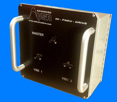
The 3D-Pneu-Drive VDW System and Process is PATENT PENDING
Our VDW System has three major ingredients:
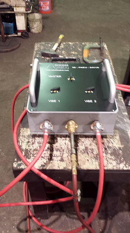
- 3D Pneu Drive control console
- Two pneumatic vibrators (two sizes are supplied for a total of four vibrators)
- Vibration meter which both gauges vibration intensity (g's) but also displays a spectrum of the vibration, so that an effective blend of vibration frequencies is generated


Tests show roughly an 85 % reduction in welding distortion.
50 foot long box beams have been welded straight within 1/4", using this technology.

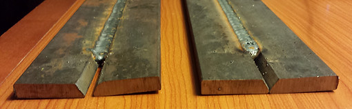
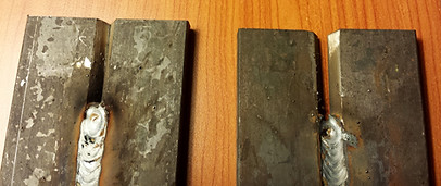
Butt welded 3/8 inch thick plates, each 2 inches wide, were welded, both with and without 3D pneumatic vibration.
Results show a large reduction in weld distortion, both in the form of plate straightness and flatness.

Gap in non-VDW'ed control piece is ~ 0.16 inch / 4 mm, while the gap in the VDW'ed test piece is less than 0.03 inch / 0.6 mm. The VDW'ed piece is also much flatter, which can be seen in the lower left photo.

70.7 ton waterway mitre gate

Elec arc furnace base VSR Processed in 3 hrs

A hydroturbine discharge ring was used as a teaching aid to VSR System operators.
70.7 ton waterway mitre gate
VIBRATORY STRESS RELIEF (VSR) is an industrial process often used to assure the dimensional stability of a metal structure. Vibratory stress relief is often used after welding and before machining. Effective vibratory stress relief causes flexure of the workpiece that combines with internal ("residual") stresses, resulting in plastic flow thru grain migration, within the material.
For many stress relief applications, effective vibratory stress relief is a suitable, at times, superior substitute, for thermal stress relief.
Metal components that have high levels of residual stress also have increased damping, which suppresses the amplitude of resonance peaks. Successful stress relief incrementally removes this suppression, allowing the peaks to grow to higher amplitudes, eventually stabilizing. Often such peak growth is accompanied by peak shifting, typically in the direction of lower frequency, but shifting to higher frequency can occur, and is often an indication of change in workpiece shape.
By recording, displaying and tuning upon these resonance peaks, the progress of a VSR Treatment can be monitored and documented. Examples of such VSR Charts can be found in the Library, in VSR Reports. There also is a Technical Library, where much of the best and pioneering research in this field can be found.
Advanced VSR isolated the phenomenon of damping reduction in the early 1980's, and has used this mechanism to design both vibratory stress relief equipment and procedures that maximize the effectiveness of the VSR Process and make easy the documentation of effective vibratory stress relief.
The slide show above shows examples of both vibratory stress relief equipment and applications.
A PARTIAL LIST OF ADVANCED VSR USERS
Lufer / Brazil
Maintec / Australia ( 2 locations )
Mainland Machinery / Canada
Martek Fabricating
Merrill Fabricators
Metalex Manufacturing
MCS / Metal Cutting Specialists
M H Eby
Mojstrovina / Slovenia
Nelson Manufacturing
Northern Valley Machine
Ormat / Israel
Polat Makina / Turkiye
PGI Steel
Precision Custom Components
R J Florig
Reading Crane
Rock Island Arsenal
Rose Corporation
Rushford Mfg
S&S Machine Shop
Sanggar Sarana Baja / Indonesia
Schoeller Bleckmann Oilfield Eqpt / Vietnam
Steward Machine
Superior Die Set
SWF Industrial
Three D Metal
Tool Room Services / Canada
Tuftco
Unique Tech Mühendislik, Turkiye
Utec Metals
Voith Hydro / USA / Brazil / Germany
WEMCO
Wendt / India
Adira / Portugal
Advanced Technologies Inc.
Alloy Engineering
Alloy Fabricators
Armadillo Press Solutions, Mexico
Anglo American /Brazil
Austin Engineering / Indonesia
Automation International
Bad Ass Band Saws
Central Machine & Pump Repair
Colonna Shipyard
Controlled Automation
Corley Manufacturing
DBC Makina / Turkiye
Dener / Turkiye
Dial Machine
Ebco International / Canada
Echo Design & Integration
E. D. Industries
Ewart-Ohlson
Extreme Machine & Fabrication
Fives / Cincinnati Machine
G & D Fabrication & Machining
Gaspar
Goodhart Sons
Goodwin International / UK
Howden / TLT Babcock
Ingersoll Machine Tools
Joyce Mech Svcs, Australia
Kadant Solutions
Keller Technology
Kovit d.o.o. / Slovenia
KOV d.o.o. / Slovenia
Longwall Associates
How Does Vibratory Stress Relief Work?
Metal components are stress relieved without the use of heat.
Instead, they undergo vibratory stress relief (VSR). This process utilizes precisely-controlled vibration to record the resonance pattern of the metal workpiece.
During VSR, peaks often grow and can shift to lower frequency. Shifts to higher frequency can indicate inevitable changes in workpiece shape.
VSR Applications
- Machine Tool Bases & Columns
- Hydroturbine Components
- Paper Mill Machinery Components
- Water Way & Storm Surge Gates
- Automotive & Aerospace Tooling
- Lifting Devices, Cranes, Yokes, & Clamshells
Why Vibratory Stress Relief?
- Cost Saving Technology
- Time & Energy Savings
- Quality Improvement
- Enhance Structure Integrity
- Control of Manufacture
- Prevent loss of physical properties caused by heat treatment
Other links to technical papers on VSR Technology :
https://app.aws.org/wj/2001/09/0049/
http://www.sciencedirect.com/science/article/pii/S1006719108600514
https://en.wikipedia.org/wiki/Vibratory_stress_relief
http://journals.sagepub.com/doi/abs/10.1177/146442070121500204