It is hard to find a milling machine worth anything these days, that does not have a brushless motor in its spindle. Brushless motor technology has also revolutionized other industries, from electric cars and trains to hand power tools.
We are the only builder of vibratory stress relief equipment in North America that uses brushless motors, which we use exclusively. Why use anything else ?
Learn more on our Equipment Comparison page.


VDW (Vibration During Welding)

VDW / Vibration During Welding, has been a method used for decades, in efforts chiefly to reduce welding distortion. Recent research has indicated that both more effective and consistent results can be obtained by using two vibrators, oriented in different directions, and running at slightly different speeds.
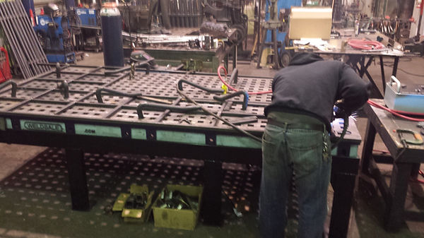
On left the two yellow vibrators are running while a welder is assembling a 12 foot long fixture, later to be used as a welding jig. Distortion was kept to less than 1/16" or 1.5 mm, which was a fraction of what had been seen before.
Note that the vibrators are pneumatic, which avoids a safety issue that occurs when using electric vibrators. In addition, these can be used at elevated temperatures, such as when preheating is required.
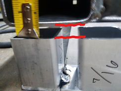
An earlier effort fabricating this frame resulted in distortion of 7/16", shown in the left photo, space between red lines.
Frames produced while using our VDW System resulted in far less distortion, on the order of 1/16" or less . . . . . . .
. . . . WHICH IS A SEVEN-FOLD DECREASE IN WELDING DISTORTION.
Contact Advanced VSR for either VDW references or an evaluation of your welding distortion issues.
Welding distortion is a common problem: A survey of fabrication shops we conducted in 2015 found that many shops spend between 5 – 10 % of their shop labor time correcting welding distortion. For many years, fabricators have vibrated fabrications during welding, in hopes of reducing distortion, with a mixed range of success.
Some manufacturers of vibratory stress relief systems, other than Advanced VSR, have claimed that their standard equipment is suitable for this task. There are a few problems with this recommendation, however, the most important being a safety issue:
Using an electrically powered vibrator, which for purposes of safety, must be electrically grounded / "earthed", while at the same time welding on metal that is electrically connected or adjacent to the vibrator, poses a risk: A loss of the welding grounded could send the high-amperage welding current thru the electric motor's ground line, which is several times too small to carry it. This could not only cause damage to the motor cable and motor, but also cause a fire to start. Keep in mind that the welder is most likely focusing on the welding, so the smell of ignition from the burning motor cable might not be immediately noticed, since the normal smells and sounds of welding would mask it.
Furthermore, our research has found that the mechanism that successfully minimizes distortion has three key ingredients:
- A mix vibration frequencies that are changing their relative phase over time
- Vibration amplitude in all three directions
- Sufficient amplitude to excite the workpiece above a threshold where distortion is minimized.
In two dimensions, the waveform that has been found to minimize welding distortion looks like this:
The blue waveform is the output of one vibrator, red from the other, which combine if properly tuned into a "modulated" waveform, which both travels down the weldment, and has both high frequency (black) and low frequency (green) components. To produce this type of waveform, and also to do so in three dimensions, requires TWO sources of vibration, i.e., two rotary vibrators, which are oriented in different directions.
To produce this type of waveform, do so in three dimensions, and DO SO SAFELY (without risk of ignition if using an electric motor powered vibrator), Advanced VSR uses pneumatic vibration, supplied by our 3D Pneu Drive VDW System (patent pending). Being pneumatically powered, the vibrators are also kept cool, so are safe to use in pre-heated applications, e.g., welding HSLA steels or weld repair of castings.
This type of waveform interferes with the pattern of highly oriented dendrites that form during freezing of a weld-puddle. You can see an example this highly oriented growth pattern below :

The 1st freezing events in a weld start in the parent metal, which works like a heat sink, quickly dissipating the heat. Patterns of dendrites grow from these locations, quickly spanning the weld seam, starting to form strength.
If a 3D version of the VDW modulated waveform is applied during the freezing event, instead of the highly directional growth pattern seen on the left, the dendrites bend and grow in a random pattern. This reduces what welders call "pull".
The 3D-Pneu-Drive VDW System and Process is PATENT PENDING
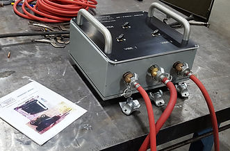
Our VDW System has three major ingredients:
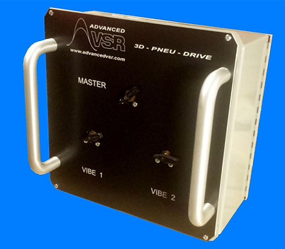
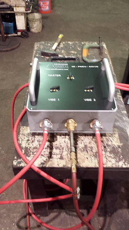
- 3D Pneu Drive control console
- Two pneumatic vibrators (two sizes are supplied for a total of four vibrators)
- Vibration meter which both gauges vibration intensity (g's) but also displays a spectrum of the vibration, so that an effective blend of vibration frequencies is generated


Tests show roughly an 85 % reduction in welding distortion.
50 foot long box beams have been welded straight within 1/4", using this technology.

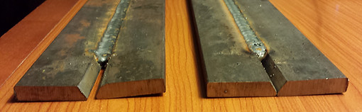
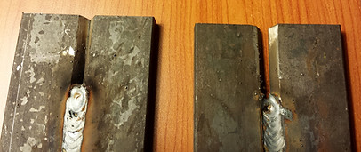
Butt welded 3/8 inch thick plates, each 2 inches wide, were welded, both with and without 3D pneumatic vibration.
Results show a large reduction in weld distortion, both in the form of plate straightness and flatness.

Gap in non-VDW'ed control piece is ~ 0.16 inch / 4 mm, while the gap in the VDW'ed test piece is less than 0.03 inch / 0.6 mm. The VDW'ed piece is also much flatter, which can be seen in the lower left photo.